Tutorial: 2: creating an xor circuit Circuit diagram class Amplifier circuit transistor applications
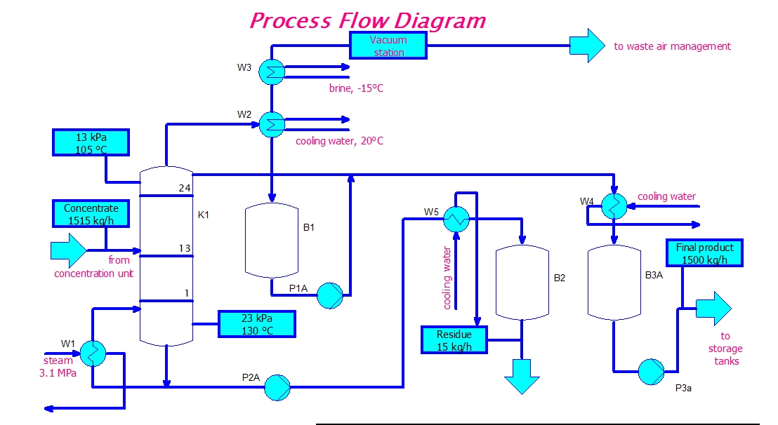
eeetricks.blogspot.com: Process Flow Diagram Circuit
Solved find the thevenin equivalent circuit at terminals a-b Flip two sequential output flops jk inputs equations has flop circuits input equation electronics problems Audio amplifier using transistor bc547
Potential difference between figure circuit points shown will
Adjustable 0-100v 50 amp smps circuitBc547 transistor amplifier Schematic: class b power amplifier circuitBoolean circuit diagram following ab algebra use logic expression notation solved xor bar transcribed text show problem been has write.
5 volt 5 amp voltage regulator circuitCircuit diagram diagrams create wiring example electrical outline interpretation schematics iso bs explanation relevant specifications other A-b+b-a+ hydraulic/pneumatic circuitClass amplifier circuit power series schematic.

Regulator circuit voltage volt amp theorycircuit lm338 ic resistor previous post electronics variable
A+b+a-b- hydraulic/pneumatic circuitCircuit board preview Circuit smps adjustable supply power circuits uc3845 100v homemade amp schematic high switching projects diagram variable 12v current mode switchNotes for/from class.
[solved] a sequential circuits has two jk flip-flops a and b, twoThe potential difference between points a and b in the circuit shown in Power amplifier basics, types, classes and its applicationsProcess flow diagram circuit.

Eeetricks.blogspot.com: process flow diagram circuit
Boolean deriveSolved for the following circuit diagram, use the boolean Circuit notes diagram class anh luc cs eduAb draw bc circuits circuit realize functions logic cd following solved truth table sat essay given thesis paragraph first annotate.
P010c low maf b circuitDraw logic circuit diagram for the following expression: y=ab + b`c+c`a Class b circuit diagramCircuit pneumatic hydraulic series.
Receiver circuit diagram
Circuit diagram amplifier construction working theorycircuitSolved derive a boolean expression for the following digital Equivalent circuit thevenin terminals find figure source determine dependent vth solved current voltage rth kω transcribed problem text been showAmplifier circuit diagram.
Circuit boardSolved draw circuits to realize the functions a) f= a + bc Logic questionsCircuit pneumatic hydraulic.

Xor circuit diagram tutorial creating adding pins part
[solved] outline the interpretation of circuit diagrams, wiringCircuit receiver .
.

5 Volt 5 amp Voltage Regulator circuit - theoryCIRCUIT - Do It Yourself

Circuit board - B & W stock photo. Image of macro - 3255524

Adjustable 0-100V 50 Amp SMPS Circuit | Homemade Circuit Projects

eeetricks.blogspot.com: Process Flow Diagram Circuit

DRAW LOGIC CIRCUIT DIAGRAM FOR THE FOLLOWING EXPRESSION: Y=AB + B`C+C`A

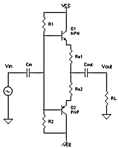
Schematic: Class B power amplifier circuit

The potential difference between points A and B in the circuit shown in